Adaptive Cruise Control, from the ISO standard to simulation
What ACC actually is per ISO 15622 — sensing, the two-loop controller, time-gap policy, the state machine — and how we test a real ACC controller as an FMU in a virtual car.
Why this post
I spent weeks integrating an adaptive-cruise-control (ACC) controller into a virtual car — and discovered that most of what I “knew” about ACC was folklore. The standards say something more precise, and occasionally the opposite. This is the write-up I wish I’d had on day one: what ACC is per the standards, how the controller is actually structured, and how to test one in simulation without a car. Key claims cite sources at the bottom, so you can go deeper on any of them.
What ACC is (and is not)
ACC drives the throttle and brake for you, with two goals: hold the driver’s set speed on an open road (classic cruise control), and keep a safe gap when there’s a lead vehicle — slowing down behind traffic, speeding back up when the lane clears. It sees ahead with radar and camera. It does not steer (lane keeping is a separate function), and it is not a safety system: per SAE J3016, ACC alone is Level 1 assistance, and even with lane centering it’s Level 2 — the driver supervises at all times [10].
That last point deserves emphasis because it shapes the whole design: ACC is comfort, not collision avoidance. Its accelerations are deliberately gentle and jerk-limited. The emergency layer is a different pair of systems — Forward Collision Warning (which alerts but never brakes) and Automatic Emergency Braking — governed by a different standard with tighter time-to-collision thresholds [11][12][13]. The three form a timeline over TTC (distance ÷ closing speed):
One piece of folklore the standard kills directly: “real ACC must have Stop & Go.” False — ISO 15622 defines two classes, FSRA (Full Speed Range, controls down to standstill, holds, restarts) and LSRA (Limited Speed Range, only works above a minimum speed and disengages below it) [1][2]. LSRA is valid ACC by the standard; Stop & Go is just today’s market default.
Sensing: radar does the heavy lifting
The workhorse sensor is the 76–77 GHz long-range radar: ~250 m of range, direct distance and closing-speed measurement via Doppler, and it works in rain, fog, and darkness [7][8][9]. The camera classifies objects, reads lane markings, and confirms radar targets; fusion combines vision’s lateral accuracy with radar’s range and speed into one environment model [14].
From there, perception reduces the world to one number that matters: the object list (distance, speed, validity per object) gets lane assignment, and the closest valid object in the ego lane becomes the target. Two small mechanisms make this robust: a range gate (objects beyond a max distance are dropped — ACC just cruises) and debounce (a briefly-occluded target isn’t dropped instantly, filtering sensor flicker). Both showed up later in our simulation testing as the parameters that most changed behavior.
The controller: two loops and a MIN
The control architecture is elegant, and the standard states it in one sentence: maintain the time gap or the set speed, whichever speed is lower [3]. Concretely:
- a speed loop computes the acceleration needed to reach the driver’s set speed,
- a distance loop computes the acceleration needed to hold the time gap behind the lead,
- a min-select takes the safer (slower) of the two,
- and the winning command is jerk-limited and clamped by speed-dependent acceleration envelopes before it goes to the actuators.
Inside the loops it’s classic control engineering: PID feedback on the gap/speed error, feed-forward of the lead’s acceleration (so you react as the lead brakes, not after the gap has already shrunk), rate limiters for comfort, and an extra gap margin against slow leads. The theory behind the constant time-gap policy — including why gaps are set in time, not meters — is the string-stability literature: disturbances must damp out along a platoon of followers rather than amplify [4][5][6].
The output is a single number: a desired acceleration (in our stack, aSoll, m/s²). Positive goes to drive torque; negative coasts, then brakes; at a full stop the parking brake can hold. One production detail I found delightful: the demand is computed twice, with diverse code, and the two results are compared — a mismatch reveals a fault in the computation itself.
The time gap: what the numbers actually are
The gap is a time, τ — target distance ≈ τ × speed. ISO 15622:2018 sets the floor: the minimum selectable gap is 0.8 s (relaxed from 1 s in 2002), and at least one selectable setting must lie in 1.5–2.2 s [1][3]. At 100 km/h those are ≈ 22 m and ≈ 42–61 m respectively.
What do real cars ship? The openACC measurement campaign [15] put actual production systems on test tracks:
| System | Measured time-gap range |
|---|---|
| ISO 15622:2018 floor | ≥ 0.8 s; one step in 1.5–2.2 s |
| Tesla | 1.3 – 2.7 s |
| BMW / Mercedes | 1.2 – 2.5 s |
| Audi | 1.2 – 3.5 s |
| Naturalistic L2 drivers [16] | often < 1 s |
Why doesn’t a 1.2 s gap end in a crash when the lead brakes? Because τ is time: the distance grows with speed, both cars decelerate together, and radar reacts in ~0.1–0.3 s where a human needs 1–1.5 s. Short gaps still cut margin — hence the mandated 1.5–2.2 s setting.
The state machine
Every ACC implementation is a state machine wearing a controller as a hat. The driver-visible states: OFF → STANDBY (ready, not controlling) → ACTIVE, where ACTIVE splits into CRUISE (road clear, hold set speed) and FOLLOW (lead ahead, hold gap), plus OVERRIDE (driver presses throttle — ACC pauses and resumes on release) and the STOP & GO cluster for FSRA: decelerate to standstill, hold the brake, wait for confirmation after a long stop, launch when the lead departs.
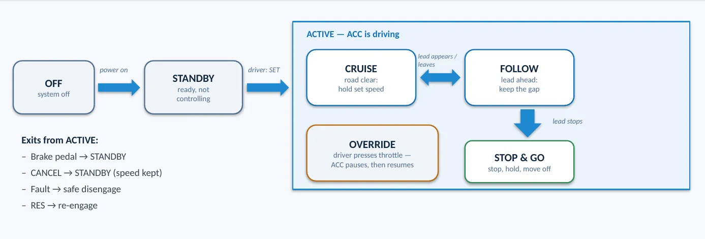 The five driver-visible modes and the transitions between them. Exits from ACTIVE — brake, CANCEL, fault — are where safety lives.
The exits from ACTIVE are where safety lives: brake pedal → immediate STANDBY; CANCEL → STANDBY with the set speed kept; a detected fault → safe disengage. The HMI maps onto this directly — SET engages and stores the current speed, RES re-engages to the stored speed, +/− steps it, a gap button cycles near/medium/far.
Under the five friendly states, a production controller hides dozens of sub-states in one byte-sized mode variable. Which is why the dynamic corner cases get their own names in every test catalog: cut-in (a car merges ahead → brake gently, re-open the gap), cut-out (lead leaves → back to set speed), target loss (occlusion → hold behavior until debounce clears), curves (slow for curvature, don’t chase out-of-lane objects). And the famous limit: a stationary object at high speed may legitimately not trigger a reaction — that’s the AEB layer’s job [1].
Testing a real controller without a car
Here’s where this connects to the virtual-car series. In a typical project the ACC controller isn’t your code — it’s a production controller model from a supplier, exported from Simulink as FMUs (Functional Mock-up Units, FMI 3.0 co-simulation): a zip with a signal-interface description plus compiled binaries. A common split is three units — HMI conditioning, the ACC brain, and a lane-occupancy/TTC observer — wired in a loop: driver wishes and the radar picture go in, one acceleration demand and dashboard status come out.
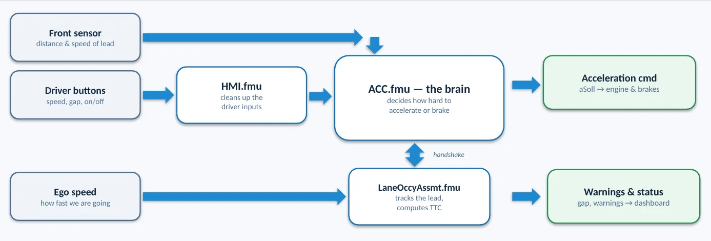 Three black boxes, one loop: HMI conditioning → the ACC brain → acceleration out, with a TTC observer alongside.
The FMU boundary is a gift for testing, because the controller becomes a black box with a typed signal interface, and you can bench it at three levels:
- Offline bench — a Python harness (
fmpy) steps the three FMUs against a scenario CSV at 100 Hz, no vehicle at all. Scenarios are just signal timelines: cut-in, slow lead, target loss (drop the object-valid flag). Assertions are behavioral: |accel| stays under 2 m/s², TTC stays above 1.5 s, the gap converges to the setting. - Calibration — the controller exposes dozens of tunable parameters (PID gains, accel envelopes, jerk limits, gap dynamics) via the automotive-standard XCP protocol and A2L description, the same mechanism a calibration engineer would use against a real ECU.
- Closed loop in the virtual car — the FMUs join the virtual vehicle as a passive bus node, CARLA provides physics, and the Android head unit provides the real HMI. The signature demo: swap the controller binary for one with a different minimum-follow-distance parameter and watch the held gap change in the 3D world — the parameter inside the binary shows up as meters on the road.
Two hard-won practical notes. Type discipline at the boundary is everything: the HMI unit outputs floats, the controller declares integer CAN types, and a scenario CSV column with the wrong type is silently ignored — the single nastiest failure mode in the whole bench. And FMU binaries are platform-specific: a vendor shipping Windows DLLs means your Linux CI needs a separate .so build — negotiate that early.
What stuck with me
ACC is a beautifully bounded problem: one output (acceleration), one policy sentence from the standard (gap or speed, whichever is slower), decades of control theory underneath, and a hard boundary against the safety layer above it. Almost everything that looks like magic in the car resolves into a small mechanism with a name — min-select, time-gap policy, debounce, override — and every one of them is testable in software long before a car exists.
References
[1] ISO 15622:2018 — Adaptive Cruise Control (FSRA/LSRA, τ policy) · [2] ISO 22179:2009 — Full Speed Range ACC · [3] ISO 15622:2002 (min-select §6.2.1) · [4] Wang & Rajamani, IEEE TVT 53(5), 2004 · [5] Rajamani, Vehicle Dynamics and Control, Springer, ch. 6 · [6] El-Baklish et al., arXiv:2402.14110 · [7] FCC, Radar Services in the 76–81 GHz Band (2017) · [8] ITU-R M.2322-0 (2014) · [9] ETSI EN 302 264 V2.1.1 · [10] SAE J3016 (2021) · [11] Euro NCAP AEB C2C Protocol v4.3.1 · [12] NHTSA, Driver Assistance Technologies · [13] ISO 22839:2013 · [14] MathWorks, ACC with Sensor Fusion · [15] Makridis et al., openACC (EC JRC), arXiv:2004.06342 · [16] Transportation Research Part C (2022), naturalistic Level-2 gaps.